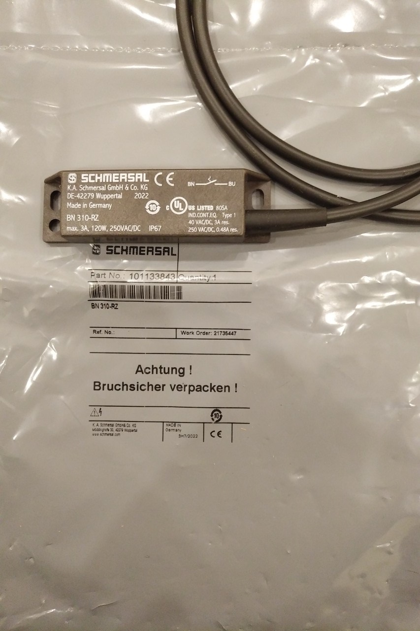
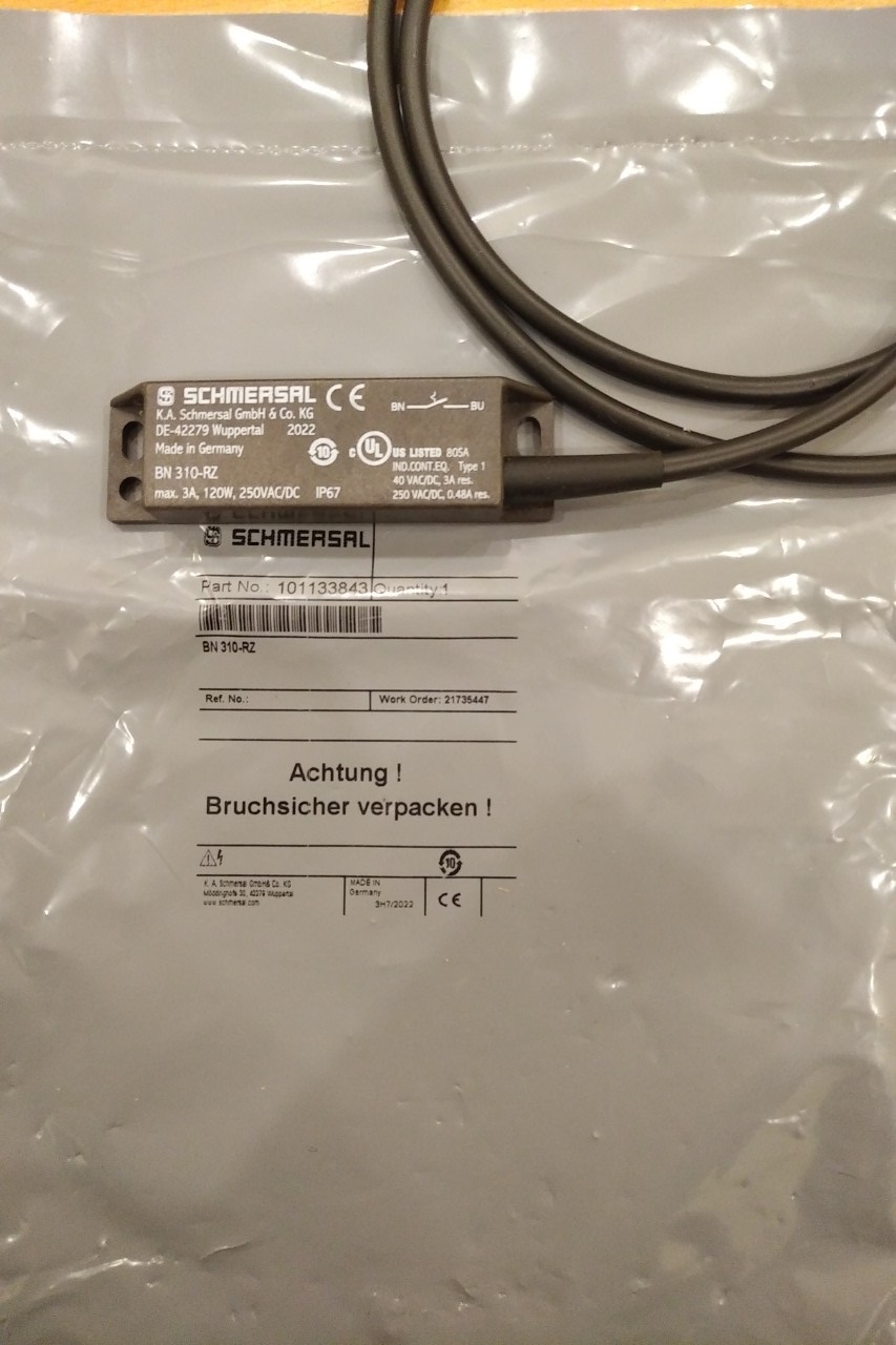
BN 310-RZ
| Ordering data | |
|
Product type description
|
BN 310-RZ |
| Article number (order number) | 101133843 |
| EAN (European Article Number) | 4,03066E+12 |
| eCl@ss number, version 11.0 | 27-27-01-05 |
| eCl@ss number, version 9.0 | 27-27-01-05 |
| ETIM number, version 7.0 | EC002544 |
| ETIM number, version 6.0 | EC002544 |
| Approvals - Standards | |
|
Certificates
|
cULus |
| General data | |
|
Working principle
|
Magnetic drive |
| Housing construction form | rectangular |
| Enclosure material | Glass-fibre, reinforced thermoplastic |
| Gross weight | 65 g |
| General data - Features | |
|
Latching
|
Yes |
| Suitable for elevators | Yes |
| Number of snap-in contacts | 1 |
| Mechanical data | |
|
Actuating panels
|
lateral |
| Actuating element | Magnet |
| Mechanical life, minimum | 1,000,000,000 Operations |
| Repeat accuracy R | 0.3 mm |
| Actuating speed, maximum | 18 m/s |
| Mounting | Enclosure with mounting slots |
| Mechanical data - Switching distances according EN IEC 60947-5-3 | |
|
Switching distance Sn
|
BP 10N = 15 mm |
| BP 10S = 15 mm | |
| 2 x BP 10N = 20 mm | |
| 2 x BP 10S = 20 mm | |
| BP 15N = 17 mm | |
| BP 15S = 17 mm | |
| 2 x BP 15/2N = 22 mm | |
| 2 x BP 15/2S = 22 mm | |
| BP 34S = 15 ... 30 mm | |
| BP 11N = 15 mm | |
| BP 11S = 15 mm | |
| BP 12N = 20 mm | |
| BP 12S = 20 mm | |
| 2 x BP 12N = 10 ... 30 mm | |
| 2 x BP 12S = 10 ... 30 mm | |
| BP 21N = 15 ... 45 mm | |
| BP 21S = 15 ... 45 mm | |
| 2 x BP 21N = 20 ... 60 mm | |
| 2 x BP 21S = 20 ... 60 mm | |
| BE 20N = 20 mm | |
| BE 20S = 20 mm | |
| 5 mm … 60 mm | |
| BP 34N = 15 ... 30 mm | |
| BP 20N = 3 ... 25 mm | |
| BP 20S = 3 ... 25 mm | |
| BP 31N = 3 ... 25 mm | |
| BP 31S = 3 ... 25 mm | |
| 2 x BP 11N = 3 ... 25 mm | |
| 2 x BP 11S = 3 ... 25 mm | |
| Note (Switching distance Sn) | Actuating distance up to 60 mm depending on actuating magnet and version. The specified switching distances are applicable for the actuation of individually mounted components without ferromagnetic influence. A change of the distance, either positive or negative, is possible due to ferromagnetic influences. The mutual interference between multiple actuating magnets must be observed. |
| Mechanical data - Connection technique | |
|
Termination
|
Cable |
| Length of cable | 1 m |
| Wire cross-section | 0.75 mm2 |
| Wire cross-section | 18 AWG |
| Material of the Cable mantle | H03VV-F |
| Mechanical data - Dimensions | |
|
Length of sensor
|
13 mm |
| Width of sensor | 88 mm |
| Height of sensor | 25 mm |
| Ambient conditions | |
|
Degree of protection
|
IP67 |
| Ambient temperature, minimum | -25 °C |
| Ambient temperature, maximum | +75 °C |
| Resistance to vibrations | 10 … 55 Hz, amplitude 1 mm |
| Restistance to shock | 30 g / 11 ms |
| Electrical data | |
|
Switching voltage, maximum
|
250 VAC |
| Switching voltage, maximum | 250 VDC |
| Switching current, maximum | 3:00 SA |
| Switching capacity, maximum | 120 W |
| Switching capacity, maximum | 120 VA |
| Switching element | bistable contact |
| Bounce duration, minimum | 0.3 ms |
| Bounce duration, maximum | 0.6 ms |
| Switching frequency, maximum | 300 Hz |
| Electrical data - Digital Output | |
|
Design of control elements
|
Reed contacts |
| Scope of delivery | |
|
Scope of delivery
|
Actuators must be ordered separately. |
| Accessory | |
|
Recommendation (actuator)
|
BP 10 S |
| 2x BP 10 S | |
| BP 15 S | |
| BP 34 S | |
| BP 20 S | |
| BP 31 S | |
| BP 11 S | |
| 2x BP 11 S | |
| BP 12 S | |
| BP 21 S | |
| 2x BP 21 S | |
| BP 10 N | |
| 2x BP 10 N | |
| BP 15 N | |
| 2 x BP 15/2 N | |
| 2x BP 15/2 S | |
| BP 34 N | |
| BP 20 N | |
| BP 31 N | |
| BP 11 N | |
| 2x BP 11 N | |
| BP 12 N | |
| 2x BP 12 N | |
| 2x BP 12 S | |
| BP 21 N | |
| 2x BP 21 N | |
| BE 20 N(S) ST 24VDC | |
| BE 20 N(S) 48VDC | |
| Recommendation (actuator, lift switchgear) | BP 10 |
| 2 x BP 15/2 | |
| 2 x BP 15 | |
| 2 x BP 10 | |
| BP 15 | |
| BP 34 |


