Danh mục sản phẩm
Hỗ trợ trực tuyến
Sản phẩm đã xem
-
 Reflex Sensor Wenglor P1NH303
-
 Danh Mục Sản Phẩm Schmersal Trong Ngành Sữa
-
 Danh Mục Sản Phẩm Schmersal Tồn Kho Có Sẵn
-
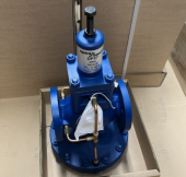
 Van SAMSON 3351
-
Bơm nhiều tầng cánh KSB Multitec V 32
-
 Endress+Hauser - PROMAG50 - 50W32-UA0A1AA0AAAA
-
 Bộ đo lưu lượng: Promag 50W32, DN32 thay thế sang Promag W 300, 5W3B32, DN32
-
 Spirax Sarco sẵn kho tại Việt Nam
Nam châm: General data Standards IEC 60947-5-3 general information Universal coding Coding level according to ISO 14119 Low Active principle RFID Housing construction form Block Installation conditions (mechanical) not flush Sensor topology S
 not flush Sensor topology S")
General data
| Standards |
IEC 60947-5-3 |
| general information |
Universal coding |
| Coding level according to ISO 14119 |
Low |
| Active principle |
RFID |
| Housing construction form |
Block |
| Installation conditions (mechanical) |
not flush |
| Sensor topology |
Sensor for series wiring |
| Enclosure material |
Plastic, thermoplastic, self-extinguishing |
| Active area |
Glass-fibre, thermoplastic |
| Gross weight |
47.4 g |
| Time to readiness, maximum |
2,000 ms |
| Reaction time, maximum |
100 ms |
| Duration of risk, maximum |
200 ms |
General data - Features
| Diagnostic output |
Yes |
| Short circuit detection |
Yes |
| Short-circuit recognition |
Yes |
| Safety functions |
Yes |
| Cascadable |
Yes |
| Integral System Diagnostics, status |
Yes |
| Number of LEDs |
3 |
| Number of semi-conductor outputs with signaling function |
1 |
| Number of fail-safe digital outputs |
2 |
Safety appraisal
| Standards |
EN ISO 13849-1 IEC 60947-5-3 EN 62061 IEC 61508 |
|
| Performance level, up to |
e |
|
| Control category to EN13849 |
4 |
|
| PFH-value |
6.80 x 10⁻¹⁰ /h |
|
|
3 |
|
| Mission Time |
20 Year(s) |
Mechanical data
| Actuating panels |
lateral front side |
| Active area |
lateral front |
| Hysteresis (Switch distance), maximum |
2 mm |
| Repeat accuracy R R |
0.5 mm |
| Note (Repeat accuracy R) |
Axial offset: The long side allows for a maximum height misalignment (x) of sensor and actuator of 8 mm (e.g. mounting tolerance or due to guard door sagging). The axial misalignment (y) is max. ± 18 mm (see figure: Operating principle). Minimum 100 mm clearance in case of approach from side. |
| Mounting |
A 20 mm screw length usually suffices to mount the sensor. When the mounting plates are used, we recommend 25 mm long screws. |
Mechanical data - Switching distances according IEC 60947-5-3
| Switch distance Sn |
front 12 mm lateral 9 mm |
| Ensured switching distance "ON", front |
10 mm |
| Ensured switching distance "OFF", front |
18 mm |
| Ensured switching distance "ON", side |
6 mm |
| Ensured switch distance "OFF" Sar, lateral |
15 mm |
Mechanical data - Connection technique
| Terminal Connector |
Connector M8 |
| Note |
The cable section of the interconnecting cable must be observed for both wiring variants! Cable length and cable section alter the voltage drop depending on the output current |
Mechanical data - Dimensions
| Length of sensor |
29.5 mm |
| Width of sensor |
39.2 mm |
| Height of sensor |
18 mm |
Ambient conditions
| Degree of protection |
IP65 to EN 60529 IP67 to EN 60529 |
| Ambient temperature, minimum |
-25 °C |
| Ambient temperature, maximum |
+65 °C |
| Storage and transport temperature, minimum |
-25 °C |
| Storage and transport temperature, maximum |
+85 °C |
| Resistance to vibrations to EN 60068-2-6 |
10 … 55 Hz, amplitude 1 mm |
| Restistance to shock |
30 g / 11 ms |
Ambient conditions - Insulation value
| Rated insulation voltage Ui |
32 VDC |
| Rated impulse withstand voltage Uimp |
0.8 kV |
| Overvoltage category |
III |
| Degree of pollution to VDE 0100 |
3 |
Electrical data
| Voltage type |
DC (direct current) |
| No-load supply current I0 |
100 mA |
| Rated operating voltage |
24 VDC -15% / +10% |
| Rated operating voltage, minimum |
20.4 VDC |
| Rated operating voltage, maximum |
26.4 VDC |
| Operating current |
600 mA |
| Required rated short-circuit current to EN 60947-5-1 |
100 A |
| Switching frequency, approx. |
1 Hz |
Electrical data - Fail-safe digital outputs
| Versions |
p-type |
| Voltage drop Ud, maximum |
1 V |
| Current leakage Ir |
0.5 mA |
| Voltage, Utilisation category DC12 |
24 VDC |
| Current, Utilisation category DC12 |
0.25 A |
| Voltage, Utilisation category DC13 |
24 VDC |
| Current, Utilisation category DC13 |
0.25 A |
Electrical data - Diagnostic output
| Versions |
p-type |
| Voltage drop Ud, maximum |
2 V |
| Voltage, Utilisation category DC12 |
24 VDC |
| Current, Utilisation category DC12 |
0.05 A |
| Voltage, Utilisation category DC13 |
24 VDC |
| Current, Utilisation category DC13 |
0.05 A |
Electrical data - Electromagnetic compatibility (EMC)
| Interfering radiation |
IEC 61000-6-4 |
| EMC rating |
IEC 60947-3 |
Status indication
| Note (LED switching conditions display) |
LED yellow: Operating condition LED green: Supply voltage LED red: Fault |
Pin assignment
| PIN 1 |
A1 Ue: White |
| PIN 2 |
X1 safety input 1: Brown |
| PIN 3 |
A2 GND: Green |
| PIN 4 |
Y1 safety output 1: Yellow |
| PIN 5 |
OUT Diagnostic output OUT Grey |
| PIN 6 |
X2 safety input 2: Pink |
| PIN 7 |
Y2 safety output 2: Blue |
| PIN 8 |
IN without function: Red |
Accessory
| Recommendation (actuator) |
RST16-1 RST-U-2 RST260-1 |
| Recommended safety switchgear |
PROTECT PSC1 SRB-E-301ST SRB-E-201LC |
General data
| Standards |
IEC 60947-5-3 |
| general information |
Universal coding |
| Coding level according to ISO 14119 |
Low |
| Active principle |
RFID |
| Housing construction form |
Block |
| Installation conditions (mechanical) |
not flush |
| Sensor topology |
Sensor for series wiring |
| Enclosure material |
Plastic, thermoplastic, self-extinguishing |
| Active area |
Glass-fibre, thermoplastic |
| Gross weight |
47.4 g |
| Time to readiness, maximum |
2,000 ms |
| Reaction time, maximum |
100 ms |
| Duration of risk, maximum |
200 ms |
General data - Features
| Diagnostic output |
Yes |
| Short circuit detection |
Yes |
| Short-circuit recognition |
Yes |
| Safety functions |
Yes |
| Cascadable |
Yes |
| Integral System Diagnostics, status |
Yes |
| Number of LEDs |
3 |
| Number of semi-conductor outputs with signaling function |
1 |
| Number of fail-safe digital outputs |
2 |
Safety appraisal
| Standards |
EN ISO 13849-1 IEC 60947-5-3 EN 62061 IEC 61508 |
|
| Performance level, up to |
e |
|
| Control category to EN13849 |
4 |
|
| PFH-value |
6.80 x 10⁻¹⁰ /h |
|
|
3 |
|
| Mission Time |
20 Year(s) |
Mechanical data
| Actuating panels |
lateral front side |
| Active area |
lateral front |
| Hysteresis (Switch distance), maximum |
2 mm |
| Repeat accuracy R R |
0.5 mm |
| Note (Repeat accuracy R) |
Axial offset: The long side allows for a maximum height misalignment (x) of sensor and actuator of 8 mm (e.g. mounting tolerance or due to guard door sagging). The axial misalignment (y) is max. ± 18 mm (see figure: Operating principle). Minimum 100 mm clearance in case of approach from side. |
| Mounting |
A 20 mm screw length usually suffices to mount the sensor. When the mounting plates are used, we recommend 25 mm long screws. |
Mechanical data - Switching distances according IEC 60947-5-3
| Switch distance Sn |
front 12 mm lateral 9 mm |
| Ensured switching distance "ON", front |
10 mm |
| Ensured switching distance "OFF", front |
18 mm |
| Ensured switching distance "ON", side |
6 mm |
| Ensured switch distance "OFF" Sar, lateral |
15 mm |
Mechanical data - Connection technique
| Terminal Connector |
Connector M8 |
| Note |
The cable section of the interconnecting cable must be observed for both wiring variants! Cable length and cable section alter the voltage drop depending on the output current |
Mechanical data - Dimensions
| Length of sensor |
29.5 mm |
| Width of sensor |
39.2 mm |
| Height of sensor |
18 mm |
Ambient conditions
| Degree of protection |
IP65 to EN 60529 IP67 to EN 60529 |
| Ambient temperature, minimum |
-25 °C |
| Ambient temperature, maximum |
+65 °C |
| Storage and transport temperature, minimum |
-25 °C |
| Storage and transport temperature, maximum |
+85 °C |
| Resistance to vibrations to EN 60068-2-6 |
10 … 55 Hz, amplitude 1 mm |
| Restistance to shock |
30 g / 11 ms |
Ambient conditions - Insulation value
| Rated insulation voltage Ui |
32 VDC |
| Rated impulse withstand voltage Uimp |
0.8 kV |
| Overvoltage category |
III |
| Degree of pollution to VDE 0100 |
3 |
Electrical data
| Voltage type |
DC (direct current) |
| No-load supply current I0 |
100 mA |
| Rated operating voltage |
24 VDC -15% / +10% |
| Rated operating voltage, minimum |
20.4 VDC |
| Rated operating voltage, maximum |
26.4 VDC |
| Operating current |
600 mA |
| Required rated short-circuit current to EN 60947-5-1 |
100 A |
| Switching frequency, approx. |
1 Hz |
Electrical data - Fail-safe digital outputs
| Versions |
p-type |
| Voltage drop Ud, maximum |
1 V |
| Current leakage Ir |
0.5 mA |
| Voltage, Utilisation category DC12 |
24 VDC |
| Current, Utilisation category DC12 |
0.25 A |
| Voltage, Utilisation category DC13 |
24 VDC |
| Current, Utilisation category DC13 |
0.25 A |
Electrical data - Diagnostic output
| Versions |
p-type |
| Voltage drop Ud, maximum |
2 V |
| Voltage, Utilisation category DC12 |
24 VDC |
| Current, Utilisation category DC12 |
0.05 A |
| Voltage, Utilisation category DC13 |
24 VDC |
| Current, Utilisation category DC13 |
0.05 A |
Electrical data - Electromagnetic compatibility (EMC)
| Interfering radiation |
IEC 61000-6-4 |
| EMC rating |
IEC 60947-3 |
Status indication
| Note (LED switching conditions display) |
LED yellow: Operating condition LED green: Supply voltage LED red: Fault |
Pin assignment
| PIN 1 |
A1 Ue: White |
| PIN 2 |
X1 safety input 1: Brown |
| PIN 3 | Đối Tác |


